
Front End Loaders For Tractors
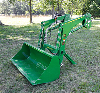
520M Loader
Overview:
- Available in non-self-leveling and mechanical self-leveling booms
- Two and Three functions available
- Hydraulics that improve cycle times and productivity
- Integrated parking stands for easy attachment and removal
Get A Quote
Fields with asterisks* are required. Please email our helpful staff with any questions or comments using the contact form.
Loan Calculator
Use the Loan Calculator to help you determine the financing and payment options that are best for you.
**The accuracy of this calculator and its applicability to your circumstances is not guaranteed. This information is provided for illustrative purposes only and does not constitute an application.
Send To A Friend
Fields with asterisks* are required. Your friend will receive an email that contains a reference to this page. Please send this email only to people you know who would be interested in this information.
Features
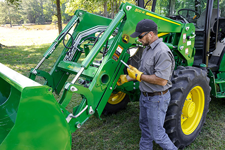
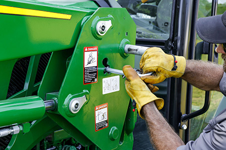
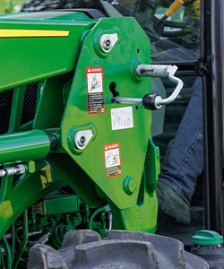
Single-point hydraulic connection saves time
 Single Point Hydraulic Connector on 5E
 Single Point Hydraulic Connector on 5E
The 520M, 540M, and H310 Loaders can be configured with a single-point hydraulic connection that also incorporates the connection point for any electrical needs. To disconnect the hydraulic connection between the loader and the tractor, it is necessary to relieve the hydraulic system oil pressure on the tractor.
Quick-Coupler connection is also an option.
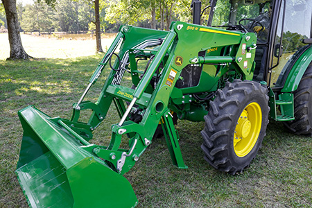
Loader removal (parking made easy)
Parking stands
John Deere loaders are easily removed and reinstalled on tractors without tools. The parking system allows removing or attaching the loader to the tractor in minutes without the need for tools.
Refer to the operator manual for complete step-by-step procedure and specific information.
An abbreviated example is listed below with some images.
To remove the loader
- Raise loader enough to allow for parking stands to be lowered and not contact ground
- Place tractor in park, exit tractor and lower parking stands and lock into position
- Tilt bucket approximately 30 degrees and apply down pressure – this down pressure allows for the parking pins to be removed / installed
- With tractor in park, exit tractor and move parking pins from locked position into open position
- Using loader joystick, adjust hydraulics to allow for loader to rest on parking stands and bucket
- Loader should remain stable on parking stands and bucket while pivoting out of the loader mounting frames
- Once loader is freely positioned, turn tractor off, rotate joystick to release pressure from connection system
- Disconnect loader hydraulic hoses from tractor
Loader raised to allow for parking stands to be lowered and locked into place for parking
Lowering Parking Stands: Parking stand pin is used to secure stand in up position during loader usage as well as lower position when being removed (parked).
With bucket tilted apply slight down pressure to the loader boom.
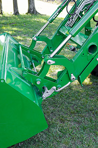
Place the locking pin into the open position for loader to allow for the loader to be removed (parking pins are designed to stay on the loader; no need to be removed completely
Loader shown removed / parked
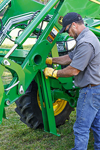
Boom lockout for easy service
 Hydraulic shut-off valve (open position)
 Hydraulic shut-off valve (closed position)
A hydraulic shut-off valve is included with the M- and H-Series Ag Loaders to ensure the loader does not lower suddenly. For example, this allows the boom to be locked out when someone is required to be located under the loader boom for service work on the tractor. It should not be used for extended periods of time unless an appropriate support stand is also utilized.
Loader suspension system (LSS) to enhance the ride
 LSS on 5E and 5M
 Operator on/off switch on 6 Series tractors
An enhancement to the loader is the suspension system. A great level of loader productivity is achieved with the LSS.
- An accumulator charged with nitrogen and connected to the head-end lift cylinder hose through a T-fitting provides shock absorption
- The cylinders move in and out to allow the boom to float
Performance
- Bales can be transported more efficiently from one end of the field to the other over frozen, hard-packed, or rutted terrain.
NOTE: Check bale-handling capability of tractor before use.
- Pallets can be moved easily without sustaining cargo damage
- Pallets of seed or fertilizer can be carried across a yard without a bag spilling and creating a costly mess
- Properly ballasted tractor with LSS has increased stability, creating a smoother ride for the operator
Cost of ownership
-
Extended life of loader pins and bushings
-
Less stress on tractor axle
Reasons for turning LSS off include:
- Digging applications - with LSS on, the cylinders retract slightly, losing lifting power
- Holding a grade when blading - with LSS on, it is difficult to hold a constant grade
- Precise pallet and bale handling - with LSS on, the load moves up and down slightly while being positioned
- Parking a loader - with LSS on, when down pressure is applied, the lift cylinders retract slightly, making it more difficult to park
The switch is conveniently located in the operator station to avoid having to exit the operator station to manually move the handle on the LSS.
LSS can also be ordered with a manual shutoff. Depending on the tractor/loader model, the accumulator is located in different places.
On the 5 Series Tractors, the accumulator is mounted near the inside of the rear right wheel.
Specifications
Key Specs
| Maximum lift height | 3343 mm 132 in. |
|---|---|
| Lift capacity at full height | Measured at pivot 1182 kg 2606 lb |
| Boom breakout force | Measured at pivot 2174 kgf 4793 lbf |
| Bucket rollback force capacity | At ground-level line 3058 kgf 6742 lbf |
| Clearance at full height - bucket dumped | 2516 mm 99.1 in. |
| Dump angle, degrees | -54 degree (angle) |
| Rollback angle, degrees | 43 degree (angle) |
Tractor
| Model | 5085E, 5090E, 5100E FT4 |
|---|---|
| Front tire | 320/85 R24 BKT (12.4 R24) |
| Rear tire | 18.4 R30 |
| Wheelbase | 90 in. |
| Pump capacity | 11 gpm |
| Rated pressure | 2828 psi |
Loader
| Base weight | 826.9 kg |
|---|---|
| Leveling configuration | Mechanical Self Leveling (MSL) |
| Bucket used | General Purpose 1850 mm 73 in. |
| Bucket weight | 178 kg 392 lb |
| Lift capacity at full height | Measured at pivot 1182 kg 2606 lb Measured at 800 mm ahead of pivot 1280 kg 2822 lb |
| Lift capacity at 59 in. (1500 mm) | Measured at pivot 1611 kg 3552 lb Measured at 800 mm ahead of pivot 1584 kg 3492 lb |
| Boom breakout force | Measured at pivot 2174 kgf 4793 lbf Measured at 800 mm ahead of pivot 1836 kgf 4048 lbf |
| Bucket rollback force capacity | At maximum height 1884 kgf 4154 lbf At 59-in. (1500-mm) lift height 3095 kgf 6823 lbf At ground-level line 3058 kgf 6742 lbf |
| Dimensions | Maximum lift height 3343 mm 132 in. At full height - bucket level 3148 mm 124 in. At full height - bucket dumped 2516 mm 99.1 in. |
| Overall length | 4.5 m 14.7 ft |
| Digging depth | 93 mm 3.7 in. |
| Reach | At maximum height 839 mm 33 in. At ground level - bucket level 2172 mm 85.5 in. |
| Bucket angle | Dump angle, degrees -54 degree (angle) Rollback angle, degrees 43 degree (angle) Dump angle, ground -109 degree (angle) |
| Cycle times | Loader raise, seconds 3.3 seconds Loader lower, seconds 2.2 seconds Bucket dump, seconds 2.6 seconds Bucket rollback, seconds 2.6 seconds |